ILS (Instrument Landing System)
In this article, we are going to identify the components of ILS, their functions, technical details and positions in an aerodrome environment.
Let’s start with what builds an ILS system?
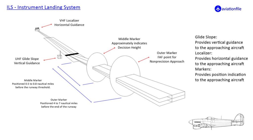
A complete ILS system has three main components which are localizer, glide path and markers. Briefly, localizer guides an airplane in horizontal position. Glide path guides in vertical position and markers indicate the position of the aircraft according to the runway in use.
(What if the Glide Path signal is unstable?)
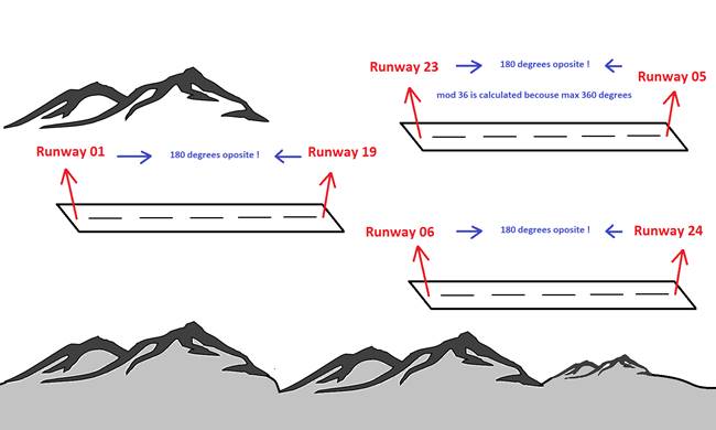
A short explanation of runway in use: Obviously one runway has two edges and this means one runway has two operational sides which are 180 degrees opposite to each other and these different sides have names which indicates the departure direction in means of heading degree. You can see the runway examples on the image below.
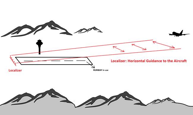
Let’s look at the Localizer:
Localizer is lateral indication component of ILS. Antennas of localizer produce frequencies between 108 and 112 Mhz. The radio beams transmitted by the Localizer antenna is received by the receiver device in the cockpit of airplane and makes the guidance of lateral position. Localizer antennas are usually located in the end of the runway in use. Moreover, it is located around 300 meters from end of the runway. See the image below.
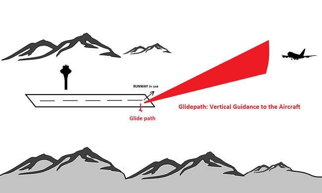
Let’s continue with glide path:
Glide Path is vertical indication component of ILS. Antenna of glide path produces frequencies between 328 – 336 Mhz. The receiver in the cockpit of the airplane receives the radio signal of the GP. Usually GP aims 3 degree descend angle to the airplane which is thought to be the smoothest and the most comfortable descent slope on final approach section. On the other hand, under exceptional circumstances (approach type, geography…) different descent slopes other than 3 degrees may be operational.
Glide path antenna is located around 100 meters left or right side of the runway in use and around 600 meters from the threshold of runway in use. See the image below.
Let’s look at the Markers:
Markers are position indication components of an ILS. Generally, there are middle and outer markers for an ILS but sometimes there can be an additional inner marker.
All marker beacons are a type of VHF (very high frequency) radio beacons. Outer marker can be located up to 7500 meters on the approach side of active runway threshold and signals a blue light indication where Middle marker can be located up to 1200 meters and signals an amber light and finally, Inner marker can be located up to 400 meters and signals a white light.
To conclude, I must add that markers are mainly for position indication and they can be combined with the other improved systems/navigation aids like DME (distance measuring equipment) or NDB (non-directional beacon) to improve the precision.
We briefly covered the ILS system and its components. Now finally let’s look at the categories of ILS classification of their precision.
| Category | Decision Height | RVR |
| I | > 200ft (60m) | > 550 m (1800 ft) or visibility > 800m (2600 ft) |
| II | 100-200ft (30-60m) | ICAO: > 350m (1200ft) FAA: 1200-2400ft (350-800m) JAA(EASA): > 300m (1000ft) |
| III A | < 100ft (30m) | > 700ft (200m) |
| III B | < 50ft (15m) | ICAO/FAA: 150-700ft (50-200m) JAA(EASA): 250-700ft (75-200m) |
| III C | no limit | none |
Maintenance and Limitations of the Instrument Landing System (ILS)
System Maintenance
To ensure the reliability of an Instrument Landing System (ILS), routine maintenance is crucial. This includes regular calibration of localizer and glide slope antennas to maintain signal accuracy. Technicians conduct periodic flight checks to validate signal alignment and strength, ensuring compliance with regulatory standards. Ground equipment, such as transmitters and marker beacons, undergoes frequent inspections to prevent malfunctions that could disrupt operations. Timely maintenance minimizes the risk of signal drift and ensures safe navigation for aircraft.
Challenges and Limitations
Despite its reliability, the ILS has certain limitations:
- Signal Interference: Structures, terrain, or other transmissions can distort signals, impacting accuracy during critical phases of landing.
- Terrain Constraints: Installation requires flat, obstacle-free areas near runways, making deployment challenging in mountainous regions or densely populated areas.
- Dependency on Infrastructure: ILS relies on expensive, ground-based infrastructure, which can be cost-prohibitive for smaller airports or regions with limited resources.
Advancements like satellite-based systems aim to address these challenges, but ILS remains an essential tool for safe and efficient landings in aviation.
References and Further Reading links:
- Mastering the fog: Instrument Landing System (ILS) explained clearly: https://en.wikipedia.org/wiki/Instrument_landing_system
- See ILS in action: Watch an explainer video on how ILS works: https://www.youtube.com/watch?v=Ngqf4qVHzBM
- Dive deeper: Explore different ILS categories and their capabilities: https://www.faa.gov/sites/faa.gov/files/InFO23001.pdf
- Beyond ILS: Discover other precision approach systems like the future-focused GNSS: https://www.faa.gov/about/office_org/headquarters_offices/ato/service_units/techops/navservices/gnss
- https://skybrary.aero/articles/instrument-landing-system-ils